
Despite this limitation, axonometric projection can be useful for purposes of illustration.

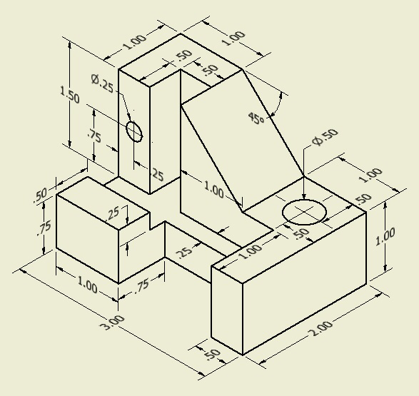
This distortion is especially evident if the object to view is mostly composed of rectangular features. Within orthographic projection, axonometric projection shows an image of an object as viewed from a skew direction in order to reveal more than one side in the same picture, unlike other orthographic projections which show multiple views of the same object along different axes.īecause with axonometric projections the scale of distant features is the same as for near features, such pictures will look distorted, as it is not how our eyes or photography work. Graphical projection is a protocol by which an image of an imaginary three-dimensional object is projected onto a planar surface without the aid of mathematical calculation.Īxonometric" means "to measure along axes". The other two types of axonometric projection are: Isometric projection is a type of axonometric projection.

"Isometric" comes from the Greek for "same measure." One of the things that makes isometric drawings so attractive is the ease with which 60 degree angles can be constructed with only a compass and straightedge.

Isometric projection corresponds to rotation of the object by ± 45° about the vertical axis, followed by rotation of approximately ± 35.264° about the horizontal axis starting from an orthographic projection view. The isometric projection show the object from angles in which the scales along each axis of the object are equal. Similar to orthographic projection, however the directions of view are different than those for orthographic projection. Not all views are necessarily used, and determination of what surface constitutes the front, back, top and bottom varies depending on the projection used. * Third angle projection is primarily used in the United States and Canada, where it is the default projection system according to BS 8888:2006, the left view is placed on the left and the top view on the top. The 3D object is projected into 2D "paper" space as if you were looking at an X-ray of the object: the top view is under the front view, the right view is at the left of the front view. * First angle projection is the ISO standard and is primarily used in Europe. The orthographic projection shows the object as it looks from the front, right, left, top, bottom, or back, and are typically positioned relative to each other according to the rules of either first-angle or third-angle projection. In most cases, a single view is not sufficient to show all necessary features, and several views are used.


 0 kommentar(er)
